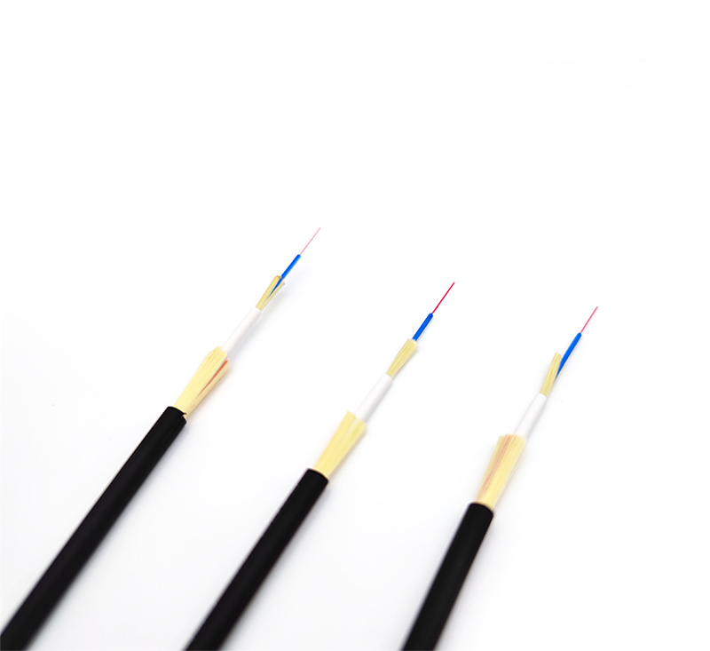
(1) The mode field diameters of the same batch of optical fibers are basically the same. After the optical fiber is disconnected at a certain point, the mode field between the two ends can be regarded as the same. The impact of losses is minimized. Therefore, fiber optic cable manufacturers are required to use the same batch of bare fibers, continuously produce them according to the required length of the fiber optic cable, serially number them on each reel, and mark the A (red) and B (green) ends respectively, without skipping numbers. When erecting the optical cable, it should be laid out according to the number along the determined routing sequence, and ensure that the B end of the optical cable in the front coil is connected to the A end of the optical cable in the next coil, so as to ensure that the mode field diameters of the two optical fiber end faces are basically the same during the connection, so that the splice loss value reach the minimum.

(2) For overhead optical cable, 72.2mm galvanized steel strand can be used as the hanging wire for hanging optical cable. Suspension wires and optical cables should be well grounded, and should have lightning and electric protection measures, as well as shock-proof and wind-proof mechanical properties. The horizontal and vertical distance between the overhead suspension line and the power line should be more than 2m, the minimum height from the ground is 5m, and the minimum distance from the roof is 1.5m. There are three types of hanging types of overhead optical cables: hanging wire hanging type, hanging wire winding type and self-supporting type. The self-supporting type does not use steel strand suspension wires, the optical cable sags, and the wind load capacity is poor, so the hanging type is commonly used.
(3) Aerial optical cable laying. Since the length of the reel of the optical cable is much longer than that of the cable, the length may reach several kilometers, so it is limited by the allowable rated tensile force and bending radius, and special attention should be paid to not yanking and kinking during construction. Generally, the allowable tensile force of the optical cable is about 150-200kg. The bending radius of the optical cable should be greater than or equal to 10 to 15 times the outer diameter of the optical cable when the cable is turned, and the bending radius should be greater than or equal to 20 times during construction and deployment. In order to avoid that the optical cable is placed in the middle of the road section, it is about 20m away from the pole and erected in opposite directions. The first half of the coil is erected, and the second half of the optical cable is put down from the reel, and placed on the ground in an "8" shape. Then deploy.
(4) When laying the optical cable, it is strictly forbidden to make small circles, fold, and twist the optical cable, and a certain number of walkie-talkies should be equipped. Also pay attention to the uniform force, the traction force does not exceed 80% of the allowable optical cable, and the instantaneous maximum traction force does not exceed 100%. In addition, when erecting, there should be a special person responsible for the turning of the optical cable or the complex terrain, and it is strictly forbidden for vehicles to roll over it. Use pulleys to lay optical cables overhead, and pre-hang pulleys on the poles and suspension lines (usually one pulley is hung every 10-20m), and reduce the sag and tension at the pulleys and pulleys of the cable. Then put the traction rope between the pulleys, the traction rope is tied to the traction head of the optical cable, and the optical cable is allowed to climb up the pole with a certain traction force and hang on the suspension line. The distance between the optical cable hooks is 40cm, the hooks on the hanging wire should be in the same direction, and there should be a convex drip groove at each pole. Each cable should have a pole length plus 3m allowance at the joint so that the box can be connected. Ground welding operation, and there must be a certain amount of coils every few hundred meters.


